Rubber Injection Mold Design: Key Principles, Materials and Common Defects
This practical guide explains how to design reliable rubber injection molding tooling, from runner and gate geometry to cavity arrangement, mold venting, thermal control, shrinkage compensation and part removal. It also examines common rubber mold defects and shows how design decisions can improve consistency, productivity and tool life.
Rubber injection molding combines precise material delivery, controlled heat and high clamping pressure to manufacture elastomer parts with repeatable dimensions and properties. Although the process resembles thermoplastic injection molding at a basic level, rubber behaves very differently inside the tool. An uncured rubber compound is viscous and elastic, begins to crosslink when exposed to heat and cannot simply be melted again after vulcanization.
These characteristics make rubber injection mold design a specialized engineering discipline. A successful tool must distribute the compound evenly, remove trapped air, maintain a controlled thermal environment, compensate for shrinkage and allow cured parts to be removed without damage. It must also resist pressure, wear, corrosion and repeated heating cycles.
A mold that produces acceptable parts during an initial trial may still be unsuitable for stable series production. Long-term performance depends on cycle consistency, cavity balance, ease of cleaning, flash control and maintainability. This guide examines the main principles of rubber injection molding tooling, including material selection, runner and gate design, cavity layout, venting, temperature control, shrinkage, demolding and defect prevention.
How Rubber Injection Molding Works
In rubber injection molding, a prepared compound is fed into an injection unit, plasticized through mechanical work and controlled heating, and delivered into a closed, heated mold. The compound flows through the sprue and runner system, enters one or more cavities and fills the available volume. Heat from the mold then accelerates vulcanization until the part has sufficient strength to be removed.
The injection unit reduces the amount of work that must occur inside the cavity. Compared with placing a cold preform directly into a compression mold, the compound arrives in a more uniform and process-ready condition. This can shorten cure time, improve material distribution and enable a greater degree of automation.
However, several events occur almost simultaneously during filling. The compound flows, deforms, heats up and may begin to cure. Air must escape as the advancing flow front reaches the ends of the cavities. If the material cures too early, fills unevenly or traps gas, defects can form before the press reaches the curing stage.
For this reason, mold design and process conditions cannot be treated separately. The tool should be designed around the selected rubber formulation, injection machine, expected production volume and required part quality.
Start with the Rubber Compound
The elastomer formulation is one of the first factors to evaluate. Natural rubber, silicone rubber, EPDM, nitrile rubber, neoprene and fluoroelastomers differ in viscosity, scorch behavior, cure temperature, shrinkage and sensitivity to contamination. Even two compounds based on the same polymer can flow differently because of their filler loading, plasticizers, curing system and processing history.
The mold designer should obtain reliable processing data before finalizing the tool. Relevant information includes compound viscosity, curing characteristics, recommended mold temperature, expected shrinkage and tendency to adhere to metal surfaces.
Scorch safety is especially important. It describes how long the compound remains processable before significant vulcanization begins. A formulation with limited scorch safety may cure prematurely in narrow gates, hot runners or areas where the flow slows down. A compound with high viscosity may require larger runners, gates and vents or higher injection pressure.
Ideally, rubber injection mold design should begin with rheometer data and representative processing trials rather than generic assumptions. Material information supplied as a broad percentage range is useful for preliminary sizing, but final shrinkage and cure conditions should be confirmed experimentally.
The Main Components of Rubber Injection Molding Tooling
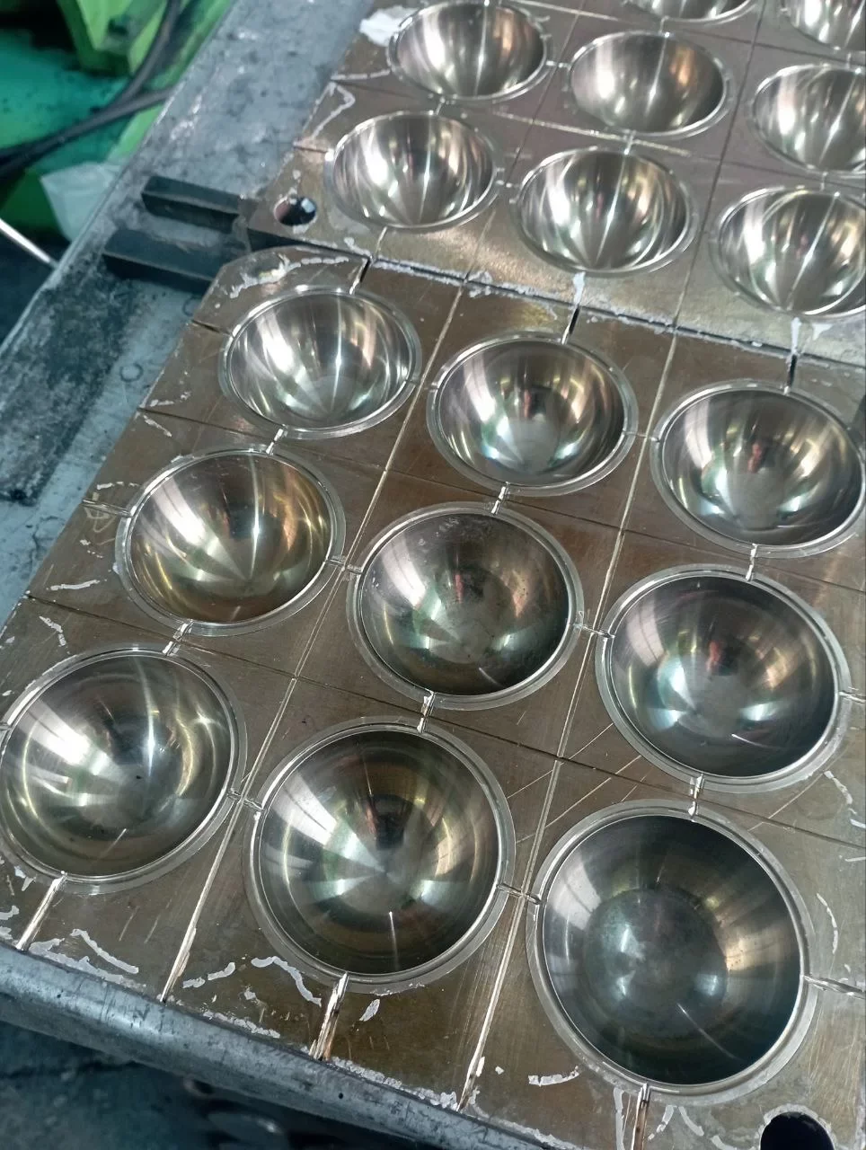
A typical injection mold contains cavity plates, core elements, a sprue or injection interface, runners, gates, vents, alignment components and a temperature-control system. Depending on the part, it may also include inserts, slides, collapsible cores, ejectors, stripping plates or removable cavity elements.
The cavity and core define the external and internal geometry of the product. The parting line separates the tool sections and affects flash location, vent placement and demolding. The feed system carries the rubber from the machine nozzle to each cavity. Venting channels remove displaced air and gases. Heating elements or thermal channels maintain the curing temperature.
Supporting plates and mold bases must withstand clamping and injection forces without excessive deflection. Even small movements at the parting surface can create flash or dimensional inconsistency. The tool should therefore be considered as a complete mechanical and thermal system, not merely a set of cavities machined into steel.
Designing the Sprue and Runner System
The sprue and runner network must carry the uncured compound to every cavity with an acceptable pressure loss and minimal risk of premature cure. The system should be as short and balanced as practical, but not so restrictive that it generates excessive shear or unstable filling.
A conventional cold-runner layout usually includes a central sprue, primary runners, secondary branches and individual gates. The runner cross-section should promote smooth flow and simplify removal of cured runner material. Full-round channels generally offer favorable flow efficiency because they have a lower surface-area-to-volume ratio than shallow channels, although they require matching grooves in both mold halves. Trapezoidal or modified semicircular runners may be easier to machine into one plate but can create different flow characteristics.
Sharp corners and sudden reductions should be avoided. Smooth transitions reduce pressure loss, heat buildup and stagnant areas where material may begin to cure. Dead zones can also retain old compound that later breaks free and contaminates molded products.
Runner dimensions depend on flow length, compound viscosity, cavity volume, injection pressure and the number of cavities. Oversized runners increase scrap and material residence time. Undersized runners require higher pressure and may produce incomplete filling or excessive shear. The optimum design balances process reliability against waste and cycle economics.
Cold-Runner and Heated-Runner Concepts
In many conventional rubber molds, the feed system cures together with the parts and is removed after every cycle. This approach is simple and robust but generates runner waste.
Cold-runner systems keep some or all of the compound below its curing temperature until it enters the heated cavities. They can reduce waste and improve cycle efficiency, particularly in high-volume production. However, they require more complex thermal isolation, accurate temperature control and careful management of material residence time.
The boundary between the cool feed zone and the heated cavity area must be stable. If too much heat enters the runner block, the compound may scorch. If the gate region is too cold, curing can become inconsistent or the gate may not separate cleanly.
Gate Design and Placement
The gate is the final restriction between the runner and the cavity. Its size and location influence filling pressure, flow direction, weld lines, air entrapment, gate marks and finishing requirements.
Common gate concepts include direct gates, edge gates, fan gates, film gates and multiple-point gates. The choice depends on part geometry and quality requirements. A direct gate can provide efficient material delivery but may leave a visible mark. An edge gate is straightforward but can create an unbalanced flow path in wide parts. Fan and film gates spread the compound over a wider area, helping to fill thin or broad sections more uniformly.
The gate should usually direct material from thicker regions toward thinner areas and push air toward deliberate venting locations. It should not force separate flow fronts to meet in a highly stressed or cosmetically critical zone.
A gate that is too small can produce excessive pressure drop, high shear and early cure. A gate that is too large may create unnecessary waste, make separation difficult or leave a prominent witness mark. Multiple gates can reduce flow distance but introduce weld lines and make balancing more difficult.
Gate design should also account for how the runner and gate will be separated from the molded part. Manual trimming may be acceptable for low-volume industrial products, while high-volume production may require automatic separation or a gate designed to tear consistently without damaging the component.
Balanced Cavity Layout
In a multi-cavity mold, all cavities should fill under similar conditions. A naturally balanced runner layout gives each cavity an equivalent flow length and comparable pressure loss. This helps produce uniform dimensions, cure state and appearance across the tool.
Geometric balance alone does not guarantee flow balance. Cavities may differ because of machining variation, temperature gradients, gate tolerances or unequal venting. Rubber compounds are sensitive to small restrictions, so a minor dimensional difference can change filling behavior.
Cavity placement must also consider the mold’s thermal layout and mechanical stiffness. Cavities positioned near the edges may lose heat differently from those near the center. Closely spaced cavities can create local heat concentration, while thin steel sections may deflect under pressure.
A practical cavity layout provides enough space for runners, vents, heaters, sensors, fasteners and cooling or insulation features. It should also allow individual cavities and inserts to be repaired or replaced where appropriate.
The designer must balance maximum cavity count against reliability. Adding more cavities may appear to increase output, but the advantage can disappear if the tool becomes difficult to heat uniformly, vent correctly or maintain.
Rubber Mold Venting
Air occupies the cavity before injection. As rubber enters, that air must escape. The process can also generate volatile substances and gases from moisture, additives or chemical reactions. Without effective rubber mold venting, these gases become compressed and may cause burns, incomplete filling, surface defects or internal voids.
Vents are usually located at the last points to fill, along the parting line and near isolated pockets. Flow analysis and short-shot trials can help identify these areas. Deep ribs, blind holes, thin sections and zones behind inserts frequently require special attention.
A vent must be deep enough to release gas but shallow enough to prevent unacceptable rubber flash. Appropriate vent dimensions depend on compound viscosity, pressure and product requirements. There is no universal vent depth suitable for every elastomer.
Vents commonly open into wider relief channels after a short, controlled land. The narrow land limits rubber escape, while the relief area allows air to move away from the cavity. The path should lead safely toward the outside of the mold rather than into a closed pocket.
Vacuum-assisted venting may be useful for complicated shapes or applications requiring very low porosity. A vacuum system removes air before or during filling, but it depends on reliable seals and correctly timed operation.
Vent maintenance is essential. Cured residue, mold-release agent and compound deposits can block shallow vents after repeated cycles. A venting system that works during initial trials may gradually lose effectiveness unless cleaning is included in the production plan.
Parting Lines and Flash Control
The parting line should be selected early because it affects cavity machining, venting, flash, appearance and part removal. Whenever possible, it should be placed away from sealing surfaces, precision edges and visible areas.
Rubber can enter very small clearances under pressure. Flash may result from worn parting surfaces, insufficient clamping force, poor alignment, excessive injection pressure or mold deflection. The tool needs rigid support, accurate guides and clean shutoff surfaces.
Flash grooves or overflow pockets may be designed beyond the cavity perimeter to receive excess material and help control pressure. These features can also assist venting, but they must be sized carefully. Excessive overflow wastes compound, while insufficient capacity may not provide consistent flash control.
The expected deflashing method should influence the design. Manual trimming, cryogenic deflashing, tumbling and precision die cutting impose different requirements on flash thickness and location.
Temperature Control and Thermal Balance
The mold must reach and maintain a temperature that allows the rubber to fill before curing and then vulcanize uniformly. Uneven temperatures can create differences in flow, cure time, dimensions and physical properties.
Heating methods may include electric cartridge heaters, heating plates, fluid channels or combinations of these systems. Heater placement should provide even energy distribution without creating local hot spots. Temperature sensors should measure conditions in representative areas, not simply at the easiest mounting location.
Thick tool sections heat slowly and retain energy, while thin sections respond faster and lose heat more readily. Cores, inserts and edge cavities may require specific attention. Machine platens, insulation plates and contact quality also affect heat transfer.
A well-designed thermal system minimizes temperature differences between cavities and across individual parts. Simulation can help predict thermal behavior, but instrumented trials remain important because the press, mold mounting and operating environment influence actual performance.
Temperature control also affects the runner system. In cold-runner tooling, the feed block must remain sufficiently cool while the cavities stay hot. Thermal barriers, cooling channels and precise control are necessary to maintain this separation.
Accounting for Rubber Shrinkage
Rubber parts change dimensions during vulcanization and cooling. The cavities are therefore typically made larger than the required final product. However, rubber shrinkage is not always uniform or perfectly predictable.
Shrinkage depends on polymer type, filler content, cure system, mold temperature, cure time, injection conditions, part thickness and post-curing. The material can also shrink differently in different directions. Metal inserts, fabric reinforcement and complex geometry may restrict movement and produce distortion.
Published shrinkage values should be treated as starting points. Whenever possible, the designer should use data from the actual production compound under representative conditions. Prototype tooling, test cavities or sacrificial steel allowances may be appropriate for critical dimensions.
The design should distinguish between dimensions that can be corrected by removing steel and those that would require adding material back to the mold. For high-risk features, leaving safe adjustment stock can reduce the cost of revisions after sampling.
Dimensional inspection should take place after the part has cooled and completed any specified post-cure. Measuring too early can lead to incorrect conclusions because elastomer dimensions may stabilize over time.
Demolding and Part Removal
A cured rubber part must be removed without tearing, permanent deformation or damage to critical surfaces. Unlike rigid thermoplastics, elastomers can stretch around undercuts, but the acceptable deformation depends on hardness, thickness, temperature and geometry.
Draft angles generally make demolding easier and reduce stress on the part. Smooth surface finishes also lower friction, although highly polished surfaces are not automatically ideal for every application. In some cases, a controlled texture improves air release or prevents excessive sticking.
Possible removal methods include manual stripping, ejector pins, stripper plates, air assist, removable inserts and collapsible cores. Ejectors should act on areas capable of supporting the load. Small pins placed under thin rubber can leave marks or puncture the product.
Undercuts must be evaluated carefully. A flexible component may be stripped from a shallow undercut, while a deeper feature may need a split cavity, movable core or collapsible mechanism. The designer should consider the rubber’s condition at the moment of ejection, because a hot part may be softer and more vulnerable to distortion.
Release agents can assist demolding, but overreliance on them may cause contamination, surface variation or interference with later bonding and painting. The preferred solution is usually a combination of suitable tool geometry, surface treatment and a stable process.
Selecting Materials for Rubber Injection Molds
Tool material selection depends on production volume, rubber formulation, pressure, operating temperature, required finish and maintenance expectations.
Prehardened tool steels offer a useful balance of machinability, strength and cost for many production molds. Hardened tool steels provide greater wear resistance and dimensional stability for long runs. Stainless grades may be selected when compounds release corrosive substances or when hygienic production and corrosion resistance are priorities.
Aluminum offers high thermal conductivity and easy machining, making it useful for prototypes and some short-run applications. Its lower wear resistance and strength may limit its suitability for demanding, high-volume production.
Surface treatments and coatings can improve wear resistance, release behavior and corrosion protection. Nitriding, hard chrome and specialized physical vapor deposition coatings are examples, but compatibility must be assessed for the compound and cleaning method.
Different sections of one tool may use different materials. Replaceable gate inserts, hardened wear plates and corrosion-resistant cavity components can provide performance where needed without making the entire mold unnecessarily expensive.
Designing for Maintenance and Tool Life
Production tooling should be easy to clean, inspect and repair. Vents, gates and runner intersections must remain accessible. Wear components and cavity inserts should be replaceable when practical.
The design should avoid narrow inaccessible recesses where cured rubber can accumulate. Fasteners, guides, seals and heater connections should be positioned for efficient service. Water or thermal-fluid channels require secure connections and corrosion-resistant construction.
Tool records should include material specifications, heat treatment, coatings, cavity dimensions, repair history and approved process settings. Good documentation reduces downtime and prevents uncontrolled modifications.
Preventive maintenance should focus on vent cleanliness, parting-line condition, gate wear, alignment, heater performance and corrosion. Cleaning methods must remove deposits without rounding sharp cavity edges or damaging surface coatings.
Common Rubber Mold Defects and Their Causes
Many rubber mold defects result from interactions between tool design, material behavior and processing conditions. Correcting them requires identifying the actual mechanism rather than changing parameters at random.
Short Shots and Incomplete Filling
A short shot occurs when the compound does not fill the entire cavity. Possible causes include restrictive gates, long flow paths, low injection volume, insufficient pressure, low compound temperature, blocked vents or premature curing.
Design solutions may include enlarging the gate, improving runner balance, shortening the flow path or adding vents at the final fill location. Process changes can help, but increasing pressure alone may create flash or tool damage.
Air Traps and Burn Marks
Compressed air can heat rapidly and produce dark burns, rough surfaces or incomplete areas. Air traps commonly occur at flow endpoints, behind inserts and where multiple fronts meet.
The primary solution is better venting. Gate relocation, modified flow paths, vacuum assistance and slower filling at critical stages may also help.
Excessive Flash
Flash forms when rubber escapes between mold surfaces. Causes include damaged parting lines, mold deflection, poor alignment, excessive material, high injection pressure and insufficient clamping force.
The solution may involve repairing shutoff surfaces, strengthening the mold structure, improving support or adjusting the feed system. Simply reducing material charge may hide the symptom while creating short shots elsewhere.
Weld Lines and Knit Marks
Weld lines form where separate flow fronts meet. They can affect appearance and mechanical performance, especially if the fronts have cooled or begun to cure.
Gate placement should move the weld line away from highly stressed regions. Better venting at the meeting point and improved thermal balance may strengthen the joint.
Voids, Blisters and Porosity
Internal voids or surface blisters may result from trapped gas, moisture, volatile ingredients, inadequate pressure or insufficient cure. Thick sections are often more vulnerable.
Potential improvements include better compound handling, vacuum venting, adjusted cure conditions and redesigned part thickness transitions.
Surface Defects and Flow Marks
Dull areas, streaks, contamination and uneven texture can result from unstable flow, dirty cavities, incompatible release agents or temperature variation. Smooth runner transitions and consistent mold cleaning help reduce these defects.
Sticking and Demolding Damage
Parts may stick because of insufficient draft, rough surfaces, deep undercuts, contamination or unsuitable mold temperature. Torn edges and distorted dimensions can also result from poorly positioned ejectors or removing the part too early.
Corrective action can include polishing selected surfaces, changing draft, revising the ejection system, applying an appropriate coating or optimizing cure time.
Dimensional Variation
Variation between cycles or cavities may be caused by unequal filling, uneven temperature, inconsistent cure, mold movement or uncontrolled post-cure. Balanced runners, rigid tool construction and representative temperature sensing are essential.
Measurement conditions must also be standardized. Rubber parts can deform under measuring force, so inspection methods should specify conditioning time, fixture design and instrument contact pressure.
Simulation, Mold Trials and Validation
Computer-aided engineering can predict filling patterns, pressure requirements, weld-line locations, air traps and temperature distribution. Simulation is particularly valuable for complex multi-cavity tools, thin sections and insert-molded components.
The accuracy of a model depends on reliable material data and realistic boundary conditions. Simulation should guide engineering decisions rather than replace trials.
Initial sampling commonly includes short-shot studies, cavity-by-cavity weight comparison, temperature mapping and dimensional inspection. Short shots reveal the actual filling sequence and help identify venting locations. Cavity weight variation can expose runner imbalance before dimensional differences become obvious.
Validation should confirm more than the appearance of a few samples. It should evaluate repeatability over multiple cycles, startup behavior, process-window sensitivity, cure consistency, demolding, flash and tool cleanliness. High-volume programs may also require capability studies and documented maintenance intervals.
Practical Design Checklist
Before releasing a rubber injection mold for manufacturing, the engineering team should confirm that:
- The actual rubber compound and cure characteristics have been reviewed.
- Runners and gates are sized for the required flow rate and pressure.
- Multi-cavity flow paths are mechanically and rheologically balanced.
- Vents are located at likely air traps and final fill points.
- The parting line avoids critical sealing and cosmetic surfaces where possible.
- The mold structure can resist clamping and injection loads.
- Heating, sensing and thermal isolation provide stable temperature distribution.
- Cavity dimensions include evidence-based shrinkage compensation.
- Draft, undercuts and ejection features support reliable demolding.
- Tool steels, coatings and treatments match the compound and production volume.
- Gates, vents and wear components are accessible for maintenance.
- The trial plan includes short shots, thermal checks and dimensional validation.
Conclusion
Effective rubber injection mold design requires coordinated control of flow, heat, pressure, curing and mechanical movement. The runner and gate system must deliver the compound evenly. The cavity layout must balance production output with thermal and structural stability. Effective rubber mold venting must remove air and gases without producing excessive flash.
At the same time, the mold must compensate for compound-specific shrinkage and release the cured component without damage. Appropriate tool steels, coatings and maintainable construction help preserve performance over long production runs.
There is no universal tooling layout suitable for every elastomer or component. Reliable rubber injection molding tooling is developed around the actual compound, machine, geometry, quality requirements and production target. When these factors are addressed together—and verified through systematic trials—the result is a wider processing window, fewer defects and more consistent manufacturing.
Supplier Sourcing Support
If you are looking for a solution in the rubber industry—whether for equipment, materials, finished products, or molds—please provide a detailed description of your requirements. Your request will be forwarded to relevant suppliers and technical specialists, allowing you to select the best option from those proposed.
Exhibition Invitation
We, Industrial Technology Exhibition, invite you to participate in the Rubber and Elastomers exhibition. Whether you're a guest or a resident company, if you have something interesting to share with our colleagues, we'll be happy to feature you on the platform. Connect, find new useful contacts, and share the latest information!
Related publications
Compression Molds vs Transfer Molds for Rubber: Which Tooling Method Should You Choose?
Compression molding and transfer molding are proven methods for manufacturing rubber components, but they differ significantly in tooling cost, material flow, production speed, precision, and design capabilities. This practical comparison explains how each process works and helps manufacturers select the right tooling method for seals, gaskets, bushings, and rubber-to-metal parts.
Read article
Rubber Molds and Dies: Types, Design and Industrial Applications
Rubber molds and dies are essential tools used to shape, form, extrude and cut rubber components. This guide explains the main rubber mold types, their design principles, advantages, limitations and industrial applications, helping manufacturers, engineers and purchasing specialists select suitable rubber tooling for each production process.
Read article
Rubber Injection Molding vs Compression Molding vs Transfer Molding
Rubber injection molding, compression molding, and transfer molding each offer different advantages in production speed, tooling investment, material efficiency, and part quality. This guide compares the three main rubber molding methods to help manufacturers select the most suitable process for their products, materials, and production volumes.
Read article
Comments 0