Compression Molds vs Transfer Molds for Rubber: Which Tooling Method Should You Choose?
Compression molding and transfer molding are proven methods for manufacturing rubber components, but they differ significantly in tooling cost, material flow, production speed, precision, and design capabilities. This practical comparison explains how each process works and helps manufacturers select the right tooling method for seals, gaskets, bushings, and rubber-to-metal parts.
Selecting a molding method is one of the most important decisions in rubber product manufacturing. The choice affects tooling investment, cycle time, material consumption, dimensional consistency, labor requirements, and the range of geometries that can be produced reliably.
Compression molding and transfer molding are both established technologies for shaping and vulcanizing thermoset elastomers. They can process many of the same rubber compounds and produce similar components, yet they introduce the material into the cavity in very different ways.
In compression molding, an uncured rubber charge is placed directly into the mold cavity before the tool closes. In transfer molding, the charge is placed in a separate chamber and forced through runners and gates into one or more closed cavities.
This difference influences nearly every production consideration. A useful compression mold vs transfer mold evaluation must therefore go beyond the initial tooling price. It should consider part geometry, annual volume, dimensional requirements, insert configuration, waste, process stability, and the total cost per acceptable component.
What Is Rubber Compression Molding?
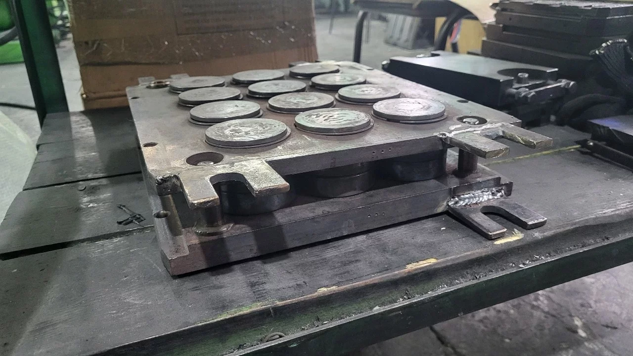
Compression molding is a relatively direct manufacturing process. A measured piece of uncured rubber, often called a preform or charge, is positioned in an open, heated cavity. The mold closes under pressure, causing the compound to flow and fill the available space. Heat and pressure are maintained until vulcanization reaches the required level.
Once curing is complete, the mold opens and the component is removed. Flash around the parting line may be trimmed manually, mechanically, or through a secondary deflashing process.
Typical compression molding stages include:
- Preparing and weighing the rubber preform.
- Loading the charge into the cavity.
- Positioning inserts when required.
- Closing the heated mold.
- Allowing the rubber to flow and cure.
- Opening the tool and removing the molded component.
- Trimming flash and performing any required post-curing.
The process is mechanically straightforward and can use relatively simple molds. For this reason, rubber compression molding tooling is frequently selected for prototypes, replacement parts, low-to-medium production volumes, large components, and products with uncomplicated geometry.
Compression molding is not limited to basic parts, but its effectiveness depends on how easily the rubber can spread from the loaded preform throughout the cavity. Long flow paths, thin sections, deep features, and delicate inserts may make cavity filling more difficult.
What Is Rubber Transfer Molding?
In transfer molding, the uncured rubber charge is loaded into a chamber called a transfer pot. The mold cavities remain closed while a plunger forces the material from the pot through sprues, runners, and gates. The compound flows into the cavities, where it is held under pressure and cured.
A typical rubber transfer molding cycle includes:
- Preparing a controlled rubber charge.
- Placing the charge into the transfer pot.
- Closing and clamping the mold.
- Activating the plunger.
- Forcing the compound through the runner system.
- Filling the closed cavities.
- Maintaining heat and pressure during vulcanization.
- Opening the tool and removing the parts.
- Separating the components from the cured runner and residual pot material.
Transfer molding introduces more tooling elements than compression molding. The mold must include the transfer chamber, plunger interface, runners, gates, vents, and cavities. These features increase engineering and manufacturing requirements, but they also provide greater control over how the rubber reaches each cavity.
Because the cavities are closed before filling, transfer molding is especially useful for intricate parts, multi-cavity tools, encapsulated inserts, and components that require controlled flow around metal elements.
How the Two Methods Differ
The principal difference is the position of the rubber before mold filling.
With compression molding, the charge starts inside the cavity. Closing pressure spreads the material until it fills the part geometry. With transfer molding, the charge starts outside the cavities and enters them through a delivery system after the mold is closed.
This distinction affects pressure distribution, operator access, cavity arrangement, flash formation, waste, and the ability to protect inserts.
Compression tooling has no transfer pot or extensive feed system, so it is generally simpler and less expensive. Transfer tooling adds complexity and produces cured material in the pot and runners, but it can fill detailed cavities more consistently and efficiently.
The best method is determined by the production application rather than by a universal hierarchy. Transfer molding is not automatically superior because it is more sophisticated, and compression molding is not always the economical choice simply because the tool costs less.
Tooling Cost
Initial investment is often a major factor when selecting between the two technologies.
Compression Mold Cost
Compression molds generally have:
- Fewer components
- Simpler machining requirements
- No transfer pot
- No plunger system
- Shorter and simpler material-flow paths
- Less complex runner and gate engineering
These characteristics usually make compression tooling more economical to design, build, modify, and repair. The lower entry cost is attractive for prototypes, small batches, legacy parts, uncertain demand, and products with large physical dimensions.
A single-cavity compression mold can also be practical when component size makes a multi-cavity transfer layout unnecessary or impossible.
However, a low tooling price should not be considered independently from operating expenses. Labor-intensive loading, inconsistent preform placement, long heating time, extensive flash, and low cavity count can make an inexpensive tool costly over its production life.
Transfer Mold Cost
Transfer molds tend to require a higher initial investment because they include:
- A transfer pot
- A precisely fitted plunger
- Sprues, runners, and gates
- More detailed venting
- Additional plates or moving elements
- Tighter alignment requirements
- More complex material-flow analysis
The design must account for the volume of the cavities, runner system, pot residue, and an appropriate excess material allowance. It must also distribute the compound evenly across multiple cavities.
Transfer tooling may therefore be difficult to justify for a short production program. For stable medium-to-high volumes, however, improved cavity utilization, more repeatable filling, reduced handling, and better part quality can offset the higher investment.
Cycle Time and Productivity
Neither process is always faster. Cycle time depends on compound rheology, cure rate, part thickness, tool temperature, cavity count, loading time, demolding, and secondary finishing.
Compression Molding Cycle Time
Compression molding may require significant operator involvement. Each cavity or mold area must receive a correctly sized charge, and inserts may need to be loaded individually. When the tool has many cavities, preform placement can extend the open-mold portion of the cycle.
Because the compound must flow within the cavity as the tool closes, the charge geometry and position affect filling time and consistency. Thick parts may also require long curing periods because heat must travel toward the center of the rubber section.
On simple components, compression molding can still be highly productive. Large flat gaskets, basic seals, pads, and low-cavity tools may have rapid loading and uncomplicated demolding. Productivity can also be improved through accurate preforming, loading fixtures, quick-change mold systems, and automated press controls.
Transfer Molding Cycle Time
Transfer molding can reduce cavity-loading time because a single rubber charge feeds multiple cavities. The material enters a closed and heated tool through relatively narrow flow passages, which can generate shear heating and improve heat transfer. Under appropriate conditions, this may support a shorter cure cycle.
The process can also provide a more repeatable filling sequence, particularly in a balanced multi-cavity design.
However, transfer molding introduces additional cycle elements. The operator or automated system must load the pot, actuate the plunger, remove the runner system, and clean any residual material from the transfer chamber. If pot residue sticks or runners are difficult to remove, these steps can reduce the productivity advantage.
For many small or moderately complex components, a well-designed multi-cavity transfer mold can produce more parts per press cycle than a comparable compression mold. The result should nevertheless be evaluated using acceptable parts per hour rather than nominal cycle time alone.
Dimensional Accuracy and Repeatability
Rubber components do not normally reach the tolerances associated with precision-machined metals because elastomers are flexible, temperature-sensitive, and affected by compound variation. Even so, tooling method strongly influences dimensional consistency.
Accuracy in Compression Molding
Compression molding can produce accurate parts when charge weight, preform geometry, loading position, mold temperature, pressure, and cure time are tightly controlled.
The process is more sensitive to charge placement because the rubber must spread through the cavity while the mold closes. If the preform is off-center or poorly shaped, one area may fill earlier than another. This can influence knit lines, trapped air, flash thickness, and local dimensions.
Variation in charge weight may also change cavity pressure and flash formation. Too little material can produce short fills. Too much can create excessive flash and increase closing resistance.
For thick, simple, or relatively forgiving parts, these limitations may be minor. For thin sections and complex geometries, they can make process control more difficult.
Accuracy in Transfer Molding
Transfer molding generally offers better control over material delivery. The closed cavity defines the part geometry before the rubber arrives, and the runner-and-gate system directs the flow in a planned sequence.
This can improve:
- Cavity-to-cavity consistency
- Filling of fine details
- Insert encapsulation
- Flash control
- Reproduction of small features
- Repeatability in multi-cavity molds
The actual results depend heavily on runner balance, gate design, venting, press control, tool condition, and compound behavior. An unbalanced transfer system can cause some cavities to fill early while others remain incomplete. Excessive pressure can move inserts or generate flash, while insufficient pressure can produce short shots or weak knit lines.
Transfer molding often has an accuracy advantage, but the method does not compensate for poor tooling design or unstable processing.
Material Waste
Material utilization is one of the clearest differences in a rubber mold comparison.
Waste in Compression Molding
Compression molding usually has no large runner network. The main source of process waste is flash around the cavity and any unused preform material.
With good charge control, optimized preforms, and properly maintained shutoff surfaces, material waste can be relatively low. This is important when processing expensive compounds such as fluoroelastomers or specialty silicones.
Some extra rubber is still required to ensure complete filling and maintain pressure during cure. Because most thermoset rubber scrap cannot be returned directly to the process as uncured compound, excessive flash has a direct effect on cost.
Waste in Transfer Molding
Transfer molding generates cured rubber in several areas:
- The residual pad in the transfer pot
- The sprue
- Distribution runners
- Gates
- Flash around the molded components
This additional material is typically removed and treated as scrap. In a poorly optimized mold, pot and runner waste may represent a significant percentage of the total shot weight, especially when the finished parts are very small.
Waste can be reduced by minimizing runner volume, selecting efficient cavity layouts, controlling the pot allowance, and increasing the number of acceptable parts produced per shot. These changes must not restrict flow or allow premature curing in the feed system.
For costly materials, the economic penalty of runner waste may outweigh the productivity and quality benefits of transfer molding. A cost calculation should therefore compare material consumed per good part, not simply nominal component weight.
Part Complexity and Design Freedom
Suitable Geometry for Compression Molds
Compression molding is commonly effective for:
- Large components
- Thick sections
- Flat or moderately contoured parts
- Simple rings and seals
- Pads and diaphragms
- Basic bushings
- Low-volume custom components
The method performs best when the charge can be placed near the center of the required material volume and when the cavity does not demand long, thin flow paths.
Undercuts can be produced using split cavities, removable cores, or other tooling features, but they increase labor and tool complexity. Very delicate features may be damaged by material movement during mold closure.
Suitable Geometry for Transfer Molds
Transfer molding is often preferable for:
- Small and detailed components
- Thin sections
- Multiple cavities
- Complex flow paths
- Closely spaced features
- Encapsulated inserts
- Rubber-to-metal bonded products
- Parts requiring better surface consistency
Because the cavities close before filling, inserts can be retained more securely than in many compression applications. The gates can also be positioned to direct flow around the inserts and reduce displacement.
Transfer molding does introduce gate marks and requires a method of separating the runner from the product. Gate position must therefore be selected carefully, particularly on sealing surfaces or visually critical areas.
Flash and Finishing Requirements
Flash affects labor, appearance, dimensions, and total production cost.
In compression molding, excess compound often escapes along the parting line during closure. Flash thickness depends on charge weight, closing speed, pressure, tool fit, compound viscosity, and mold wear. Components with long perimeters or complicated parting lines may require extensive trimming.
Transfer molding can provide better flash control because the mold is already closed when material enters the cavity. Well-designed shutoffs help limit rubber migration between mold surfaces.
Nevertheless, transfer molding does not eliminate flash. High transfer pressure, worn parting surfaces, excessive material volume, or insufficient clamping force can still produce it. The gate vestige and runner attachment also create an additional finishing consideration.
When estimating cost, manufacturers should account for manual trimming, cryogenic deflashing, tumbling, inspection, and scrap caused by trimming damage.
Process Control and Automation
Both methods can be automated, but their automation requirements differ.
Compression molding automation may include:
- Automatic preform cutting
- Robotic charge placement
- Insert-loading fixtures
- Automated mold opening
- Ejector or stripper systems
- Robotic part removal
- Integrated deflashing
Reliable automation depends on consistent preform dimensions and predictable placement. Soft, tacky preforms may be difficult to feed and position automatically.
Transfer molding can centralize material loading because one charge feeds several cavities. Presses can control transfer pressure, plunger speed, tool temperature, cure time, and decompression. Automated runner removal and part extraction may also be incorporated.
The more complex tool structure requires disciplined maintenance. Gates and vents can become restricted by cured deposits, and wear in the pot or plunger can affect transfer pressure and material leakage.
For either process, automation is economically attractive when annual volume and quality savings justify the additional equipment and engineering.
Comparison for Seals
The term “seal” covers a broad range of components, so the final choice depends on geometry and performance requirements.
Compression molding is often suitable for:
- Large-diameter seals
- Thick sealing rings
- Low-volume custom seals
- Simple static sealing elements
- Replacement parts
- Products made from expensive compounds where runner waste must be minimized
Transfer molding may be better for:
- Small precision seals
- Multi-lip geometries
- Thin sealing edges
- High-cavity production
- Parts with detailed profiles
- Seals bonded to rigid inserts
Critical sealing edges should be kept away from undesirable parting lines and gate locations. If a transfer gate must enter near a functional surface, its removal and vestige tolerance must be clearly defined.
For large, straightforward seals, compression tooling often provides the best economic result. For small, detailed seals requiring consistent cavity filling, transfer molding can offer better process capability.
Comparison for Gaskets
Gaskets are often flat and relatively simple, making them natural candidates for compression molding. A multi-cavity compression tool can produce several pieces with minimal runner waste, while the broad cavity area supports direct material placement.
Compression molding is especially practical for:
- Flat gaskets
- Flange gaskets
- Low-to-medium production volumes
- Large gasket dimensions
- Relatively uniform thickness
- Simple holes and contours
Transfer molding may be justified when a gasket includes narrow ribs, complex cross-sections, multiple thickness transitions, fine sealing beads, or bonded inserts.
The engineer should also consider whether molding is necessary. Some flat gaskets may be more economical to die-cut from cured sheet. Molded tooling becomes attractive when the gasket requires three-dimensional details, controlled edge profiles, integral beads, or material properties that cannot be obtained efficiently from sheet stock.
Comparison for Bushings
Rubber bushings range from simple cylindrical parts to complex bonded assemblies.
Compression molding can be a practical choice for:
- Plain rubber bushings
- Thick-walled cylindrical components
- Low production volumes
- Large bushings
- Designs with simple cores
- Products with broad dimensional tolerances
The charge can be positioned around a mandrel or in the cavity, after which the mold closes and forms the final shape. Careful charge design is necessary to avoid air entrapment and nonuniform flow.
Transfer molding may provide advantages for smaller bushings, thin sections, multiple cavities, or components containing inner and outer metal sleeves. Controlled flow can distribute rubber around the sleeves and into narrow annular spaces.
When bonding rubber to metal, insert preparation is essential regardless of the molding method. Cleaning, surface treatment, adhesive application, drying, storage, and handling must be controlled. Even a well-designed mold cannot compensate for contaminated or improperly prepared inserts.
Comparison for Rubber-to-Metal Parts
Rubber-to-metal products include vibration isolators, mounts, bonded bushings, rollers, seals, diaphragms, and encapsulated hardware.
Transfer molding is frequently selected because the closed mold can hold inserts in defined positions while the compound flows around them. It is particularly useful when the design includes:
- Multiple metal inserts
- Narrow spaces around inserts
- Complex bonding surfaces
- Thin rubber layers
- High cavity counts
- Tight requirements for insert position
- A need for controlled flow around delicate features
Compression molding remains effective for larger or simpler rubber-to-metal components. It may minimize runner waste and use less expensive tooling. The process is viable when the insert can be retained securely and when the rubber charge can fill the cavity without shifting the metal component.
Insert movement is a critical risk in both processes. The tool should positively locate the metal element, resist molding pressure, allow air to escape, and prevent adhesive damage during loading. Pin marks, locating features, and acceptable exposed-metal areas must be agreed upon during design.
Maintenance and Tool Life
Compression molds are typically easier to disassemble, clean, and repair. Their simpler construction reduces the number of feed channels and interfaces that can wear or accumulate deposits.
Common maintenance tasks include:
- Cleaning cavity surfaces
- Clearing vents
- Inspecting parting lines
- Checking ejectors and removable cores
- Repairing damaged shutoffs
- Verifying plate flatness and alignment
Transfer molds require the same work plus inspection of the pot, plunger, sprues, runners, and gates. Gate dimensions can change through wear or cleaning damage, affecting fill balance. Residue in runners or vents may cause short shots, burns, or inconsistent cavity pressure.
Maintenance accessibility should be considered at the design stage. Replaceable inserts at gates, high-wear shutoffs, and vulnerable cavity details can reduce repair time and extend the useful life of the tool.
Total Cost per Part
The most appropriate economic measure is the total cost per acceptable part over the planned production volume.
A complete analysis should include:
- Mold design and manufacturing cost
- Press and auxiliary equipment cost
- Tool validation expense
- Rubber consumption
- Pot, runner, gate, and flash waste
- Preform preparation
- Insert preparation and loading
- Cycle time
- Number of cavities
- Operator labor
- Energy consumption
- Trimming and deflashing
- Inspection
- Scrap rate
- Maintenance and repair
- Tool-change downtime
- Expected tool life
Compression molding often has a lower break-even threshold because the initial tooling investment is smaller. Transfer molding may achieve a lower unit cost at higher volumes when multi-cavity productivity, consistency, and reduced handling compensate for added tooling and material waste.
The break-even point varies significantly among applications. It should be calculated using actual production assumptions rather than a general rule.
Advantages and Limitations at a Glance
Compression Molding Advantages
- Lower initial tooling cost
- Simple mold construction
- Relatively easy maintenance
- Minimal runner-system waste
- Suitable for large and thick components
- Economical for prototypes and lower volumes
- Effective for simple seals, gaskets, and bushings
Compression Molding Limitations
- Greater dependence on preform weight and position
- More manual cavity loading
- Potentially higher parting-line flash
- Limited control over long or thin flow paths
- More difficult filling of intricate details
- Possible insert movement during closure
Transfer Molding Advantages
- Better control of material flow
- Good reproduction of fine features
- Suitable for multi-cavity production
- Strong option for insert molding
- Improved cavity-to-cavity consistency
- Potentially reduced cavity-loading time
- Effective for complex rubber-to-metal products
Transfer Molding Limitations
- Higher tooling cost
- More complex design and maintenance
- Additional waste from the pot and runners
- Gate marks on molded parts
- Greater dependence on runner balance
- Additional steps for runner and residue removal
How to Choose the Right Tooling Method
Compression molding is usually the stronger candidate when the component is large, thick, relatively simple, produced in low or moderate volumes, or made from an expensive compound where runner waste must be minimized. It is also suitable when a low initial tooling budget and quick mold construction are major priorities.
Transfer molding deserves serious consideration when the part is small, detailed, thin, insert-intensive, or produced in a high-cavity layout. It is often advantageous when consistent filling and precise control around metal inserts are more important than minimizing tooling cost and runner waste.
Before making the final selection, the manufacturing team should answer several practical questions:
- What annual volume is expected during the program life?
- How complex are the geometry and flow paths?
- What dimensional and cosmetic requirements must be achieved?
- Does the design contain inserts or bonded metal elements?
- How expensive is the rubber compound?
- What percentage of the shot will become process waste?
- How many cavities can the press and mold support?
- What loading and demolding operations will require labor?
- How much trimming will each process generate?
- Is automation planned now or in the future?
- What tooling maintenance resources are available?
- Which method delivers the lowest cost per approved part?
Early trials or process simulation may be justified for demanding components. Evaluating both alternatives before finalizing the product geometry can also reveal design changes that reduce tooling complexity and improve manufacturability.
Conclusion
The compression mold vs transfer mold decision depends on the complete manufacturing case rather than one isolated parameter. Compression molding generally offers simpler and less expensive tooling, lower runner waste, and good suitability for large, thick, or straightforward components. Transfer molding usually provides more controlled material delivery, stronger multi-cavity capability, and better support for fine details and rubber-to-metal assemblies.
For basic gaskets, large seals, and plain bushings, rubber compression molding tooling is often the practical and economical solution. For precision seals, complex bushings, intricate geometries, and insert-intensive products, rubber transfer molding may provide better quality and repeatability.
A reliable rubber mold comparison should evaluate investment, cycle productivity, material loss, finishing labor, maintenance, scrap, and expected production volume. The best tooling method is the one that consistently meets product requirements at the lowest total cost per acceptable component.
Supplier Sourcing Support
If you are looking for a solution in the rubber industry—whether for equipment, materials, finished products, or molds—please provide a detailed description of your requirements. Your request will be forwarded to relevant suppliers and technical specialists, allowing you to select the best option from those proposed.
Exhibition Invitation
We, Industrial Technology Exhibition, invite you to participate in the Rubber and Elastomers exhibition. Whether you're a guest or a resident company, if you have something interesting to share with our colleagues, we'll be happy to feature you on the platform. Connect, find new useful contacts, and share the latest information!
Related publications
Rubber Injection Mold Design: Key Principles, Materials and Common Defects
This practical guide explains how to design reliable rubber injection molding tooling, from runner and gate geometry to cavity arrangement, mold venting, thermal control, shrinkage compensation and part removal. It also examines common rubber mold defects and shows how design decisions can improve consistency, productivity and tool life.
Read article
Rubber Molds and Dies: Types, Design and Industrial Applications
Rubber molds and dies are essential tools used to shape, form, extrude and cut rubber components. This guide explains the main rubber mold types, their design principles, advantages, limitations and industrial applications, helping manufacturers, engineers and purchasing specialists select suitable rubber tooling for each production process.
Read article
Rubber Injection Molding vs Compression Molding vs Transfer Molding
Rubber injection molding, compression molding, and transfer molding each offer different advantages in production speed, tooling investment, material efficiency, and part quality. This guide compares the three main rubber molding methods to help manufacturers select the most suitable process for their products, materials, and production volumes.
Read article
Comments 0